
 Menu
Menu
- Minicomputer(81)
- Microcontroller(89)
- Electronic(531)
- Enclosures(8)
- Cooling(22)
- Sound and acoustics(11)
- Minicomputers(3)
- Memory cards and disks(6)
- Sensors(58)
- Voltage regulators(42)
- Assembly electronics(79)
- Programmers(12)
- Displays and screens(28)
- Buttons and keys(23)
- Starter kits(8)
- Diodes(8)
- Converters(29)
- Power supply(60)
- Battery accessories(21)
- Chargers(26)
- Gadgets(1)
- LED lighting(12)
- Relays(25)
- GSM modules(4)
- Motor and servo controllers(14)
- Communication(63)
- Servo(5)
- Smart Home(2)
- Services(0)
- New products









USB-C PD QC 100W 5A 5V–20V LED Fast Charging Trigger Module
 0
0
Description
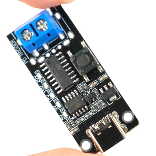
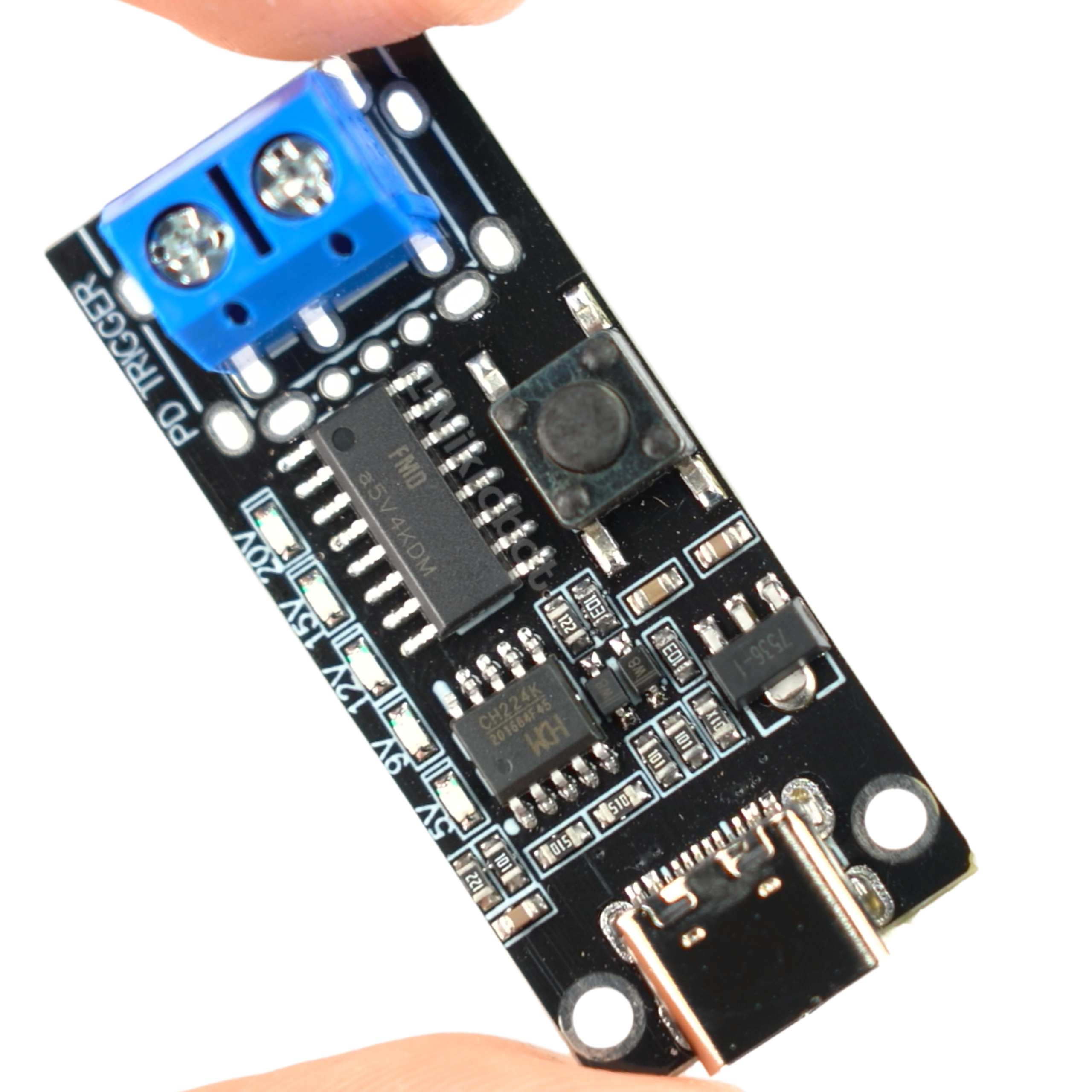
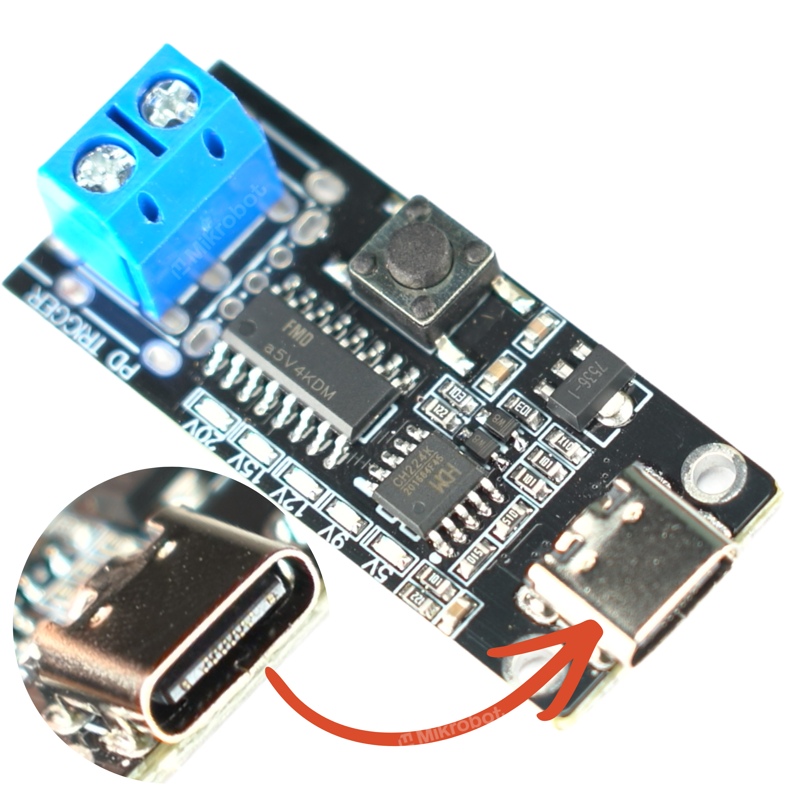
The advanced Type-C fast-charging trigger module is a precision tool designed to force voltage from power supplies that support modern protocols. The circuit supports popular standards, including Power Delivery 3.0 (PD3.0) and Quick Charge 3.0 (QC3.0), as well as FCP and AFC. It is ideal for advanced power supply systems and laboratory setups.
The device features a USB-C input port supporting a current of up to 5A, allowing for power delivery of up to 100W. The output is provided via a sturdy screw-type connector, ensuring a secure connection for the cables. Built-in LED indicators provide real-time information on the selected voltage level.
Key Technical Features
The board is characterized by high performance and configuration flexibility. The built-in logic circuit enables proper negotiation with the charger without user intervention after a one-time setting of the appropriate power threshold.
- Output voltage range: 5V / 9V / 12V / 15V / 20V
- Maximum current load: 5A
- Maximum supported power: 100W (when using a cable with an E-marker; otherwise, max 60W)
- Supported protocols: PD3.0, QC3.0, FCP, AFC
- Input connector type: USB Type-C
- Output connector type: screw-type
- Visual indicators: LEDs for each voltage level
- Exact module dimensions: 42.4 x 18.1 mm
- Device weight: 5 g
Example Applications
- Powering universal electronic projects and prototypes assembled on breadboards.
- Providing a stable voltage to the ESP8266, ESP32, Arduino, and Raspberry Pi.
- Verifying parameters and rigorously testing USB-C chargers for fast-charging protocols.
- Powering minicomputers, routers, and electronics requiring voltages ranging from 5V to 20V.
- A professional diagnostic tool for workshops, technical service centers, and laboratories.
Advanced voltage configuration
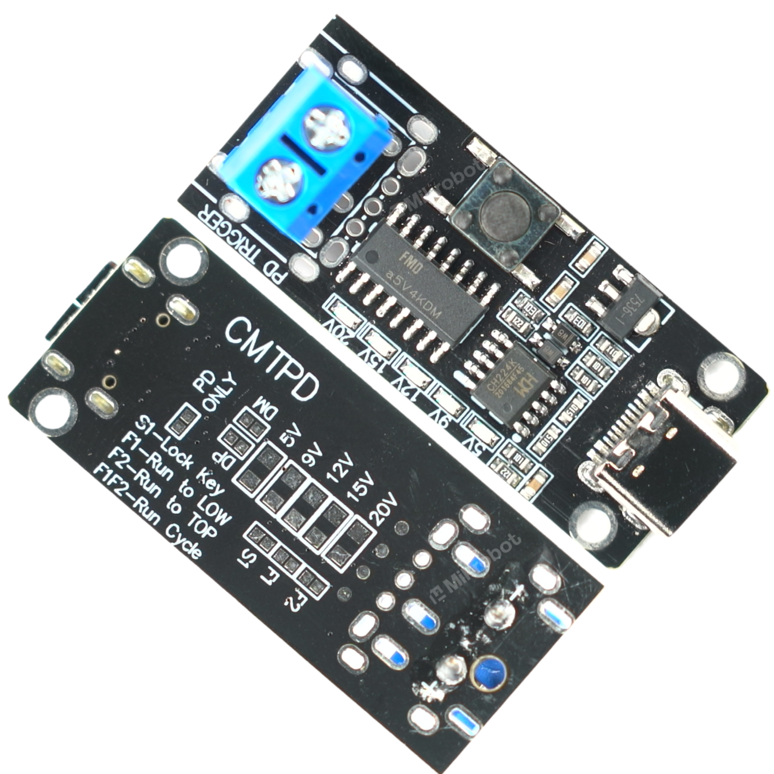
In addition to the standard 5–20V output, the module provides additional solder pads that allow for precise customization of its operation to a specific application:
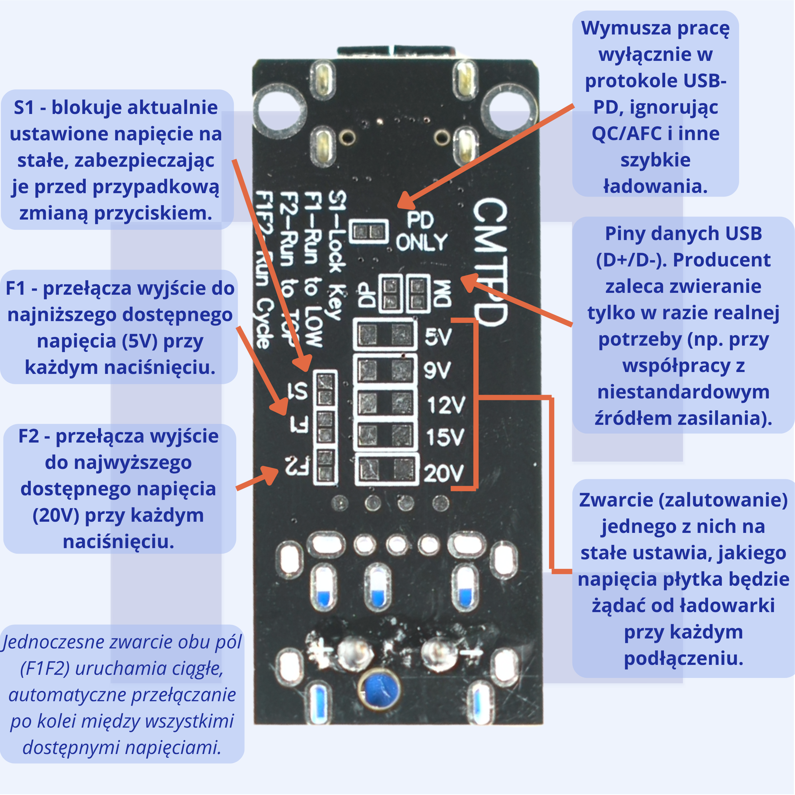
- Fixed voltage selection (5V/9V/12V/15V/20V pads) — soldering one of the pads sets the output once and for all. Ideal when the module is intended to power a single specific device (e.g., a 12V router, a 20V laptop).
- PD ONLY – forces operation exclusively in the USB-PD protocol, bypassing QC/AFC/FCP. Useful for testing chargers for pure PD compliance.
- Dynamic mode with a button (S1/F1/F2 pads)—after soldering on an external micro-switch, the voltage is controlled “on the fly,” without having to re-solder:
- F1 – automatically cycles through all voltages from highest to lowest,
- F2 – from the lowest to the highest,
- F1+F2 together—continuous, repetitive switching between all voltages (quick test of the entire range),
- S1 – locks the currently set voltage, preventing accidental changes.
How to Use This in Practice
- Service and diagnostics: The F1/F2 button lets you check in a few seconds what voltages a given charger or power bank actually offers—without having to manually switch anything.
- DIY projects: Soldering one voltage pad turns the module into a simple, fixed-voltage power supply for a specific circuit.
- Testing and laboratory applications: The combination of the button and the S1 lock allows you to quickly test a device at several voltages and then lock it to a safe level before passing the equipment on.
Benefits of Using the Module
Using the trigger module allows for a significant reduction in the number of workshop power supplies needed. Check out the benefits this circuit offers:
- High versatility—support for multiple standards and voltage ranges allows you to power various devices using just a single cable.
- Safe installation—the permanently soldered screw terminal prevents the load from accidentally disconnecting during operation.
- Instant diagnostics—integrated indicator lights provide immediate feedback on the voltage set by the controller.
- Easy integration—with dimensions of 42.4 x 18.1 mm, the module fits easily inside small enclosures.
- Power supply safety—built-in hardware protection mechanisms in the supported protocols reduce the risk of receiver failure.
ℹ Note
- The specified parameters represent the module’s maximum capabilities—the actual voltage, current, and power depend on the profiles actually offered by the connected charger or power bank.
- Before connecting, check the available voltages on your power supply in the “Output” section on the housing.
- The device is not a voltage converter, but a trigger that forces the power supply to output a specific voltage.
Product reviews (0)

All reviews (positive and negative) are displayed. We don't verify that they come from customers who have purchased the product.