
 Menu
Menu
- Minicomputer(81)
- Microcontroller(89)
- Electronic(531)
- Enclosures(8)
- Cooling(22)
- Sound and acoustics(11)
- Minicomputers(3)
- Memory cards and disks(6)
- Sensors(58)
- Voltage regulators(42)
- Assembly electronics(79)
- Programmers(12)
- Displays and screens(28)
- Buttons and keys(23)
- Starter kits(8)
- Diodes(8)
- Converters(29)
- Power supply(60)
- Gadgets(1)
- LED lighting(12)
- Relays(25)
- GSM modules(4)
- Motor and servo controllers(14)
- Communication(63)
- Servo(5)
- Smart Home(2)
- Services(0)
- New products









Konwerter USB-UART CH343P TTL RTS DTR 3.3V 5V do ESP32 ESP8266 Arduino
 0
0
Description
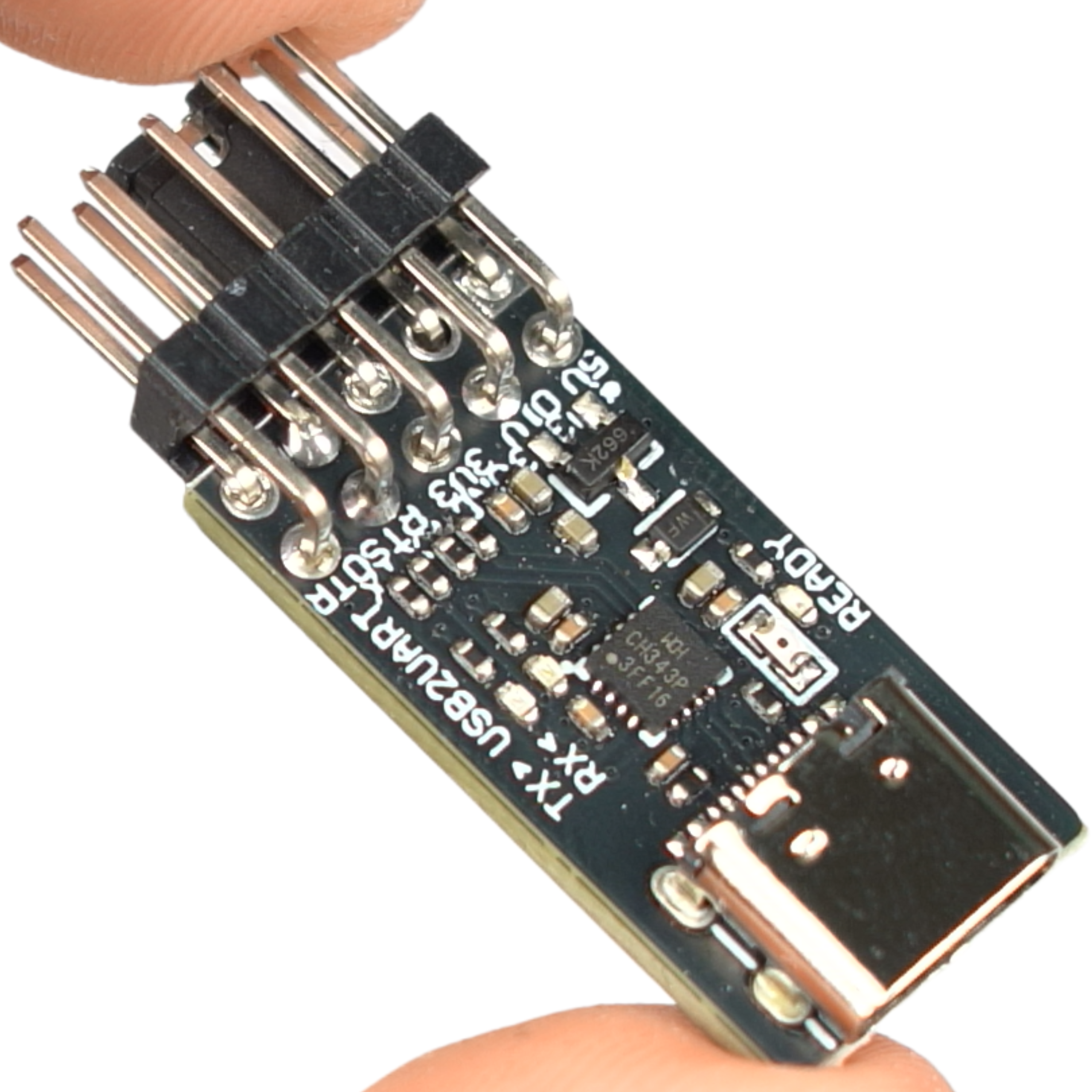
CH343P USB-UART Converter with RTS and DTR for ESP8266, ESP32, Arduino, and Raspberry Pi
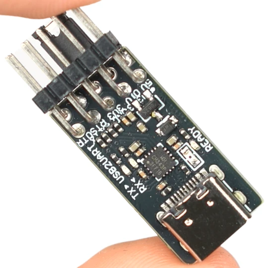
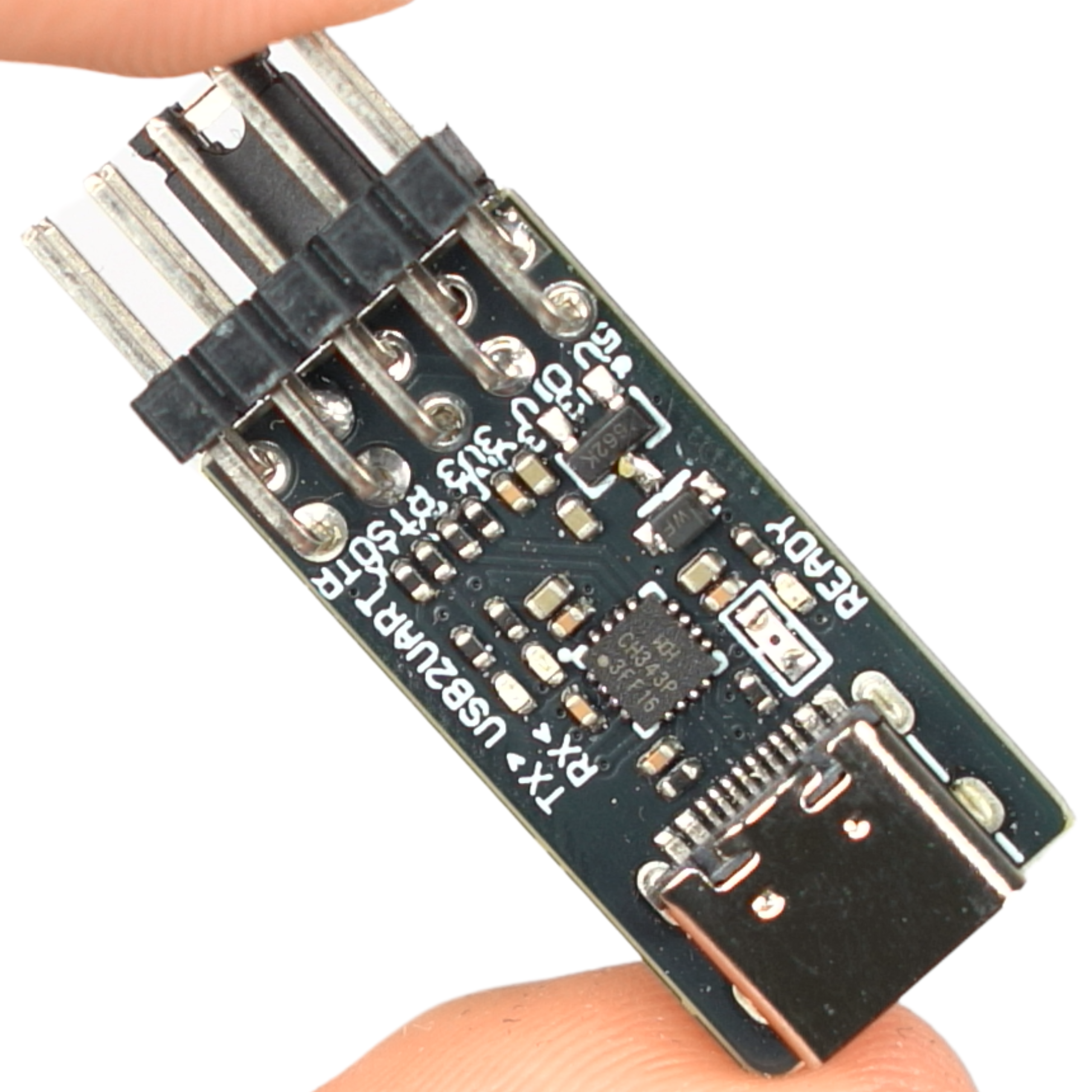
A USB-UART converter module based on the CH343P chip. It enables reliable serial communication with microcontrollers, development boards, and embedded devices. The version with additional RTS and DTR lines allows for automatic programming of chips without manual resets.
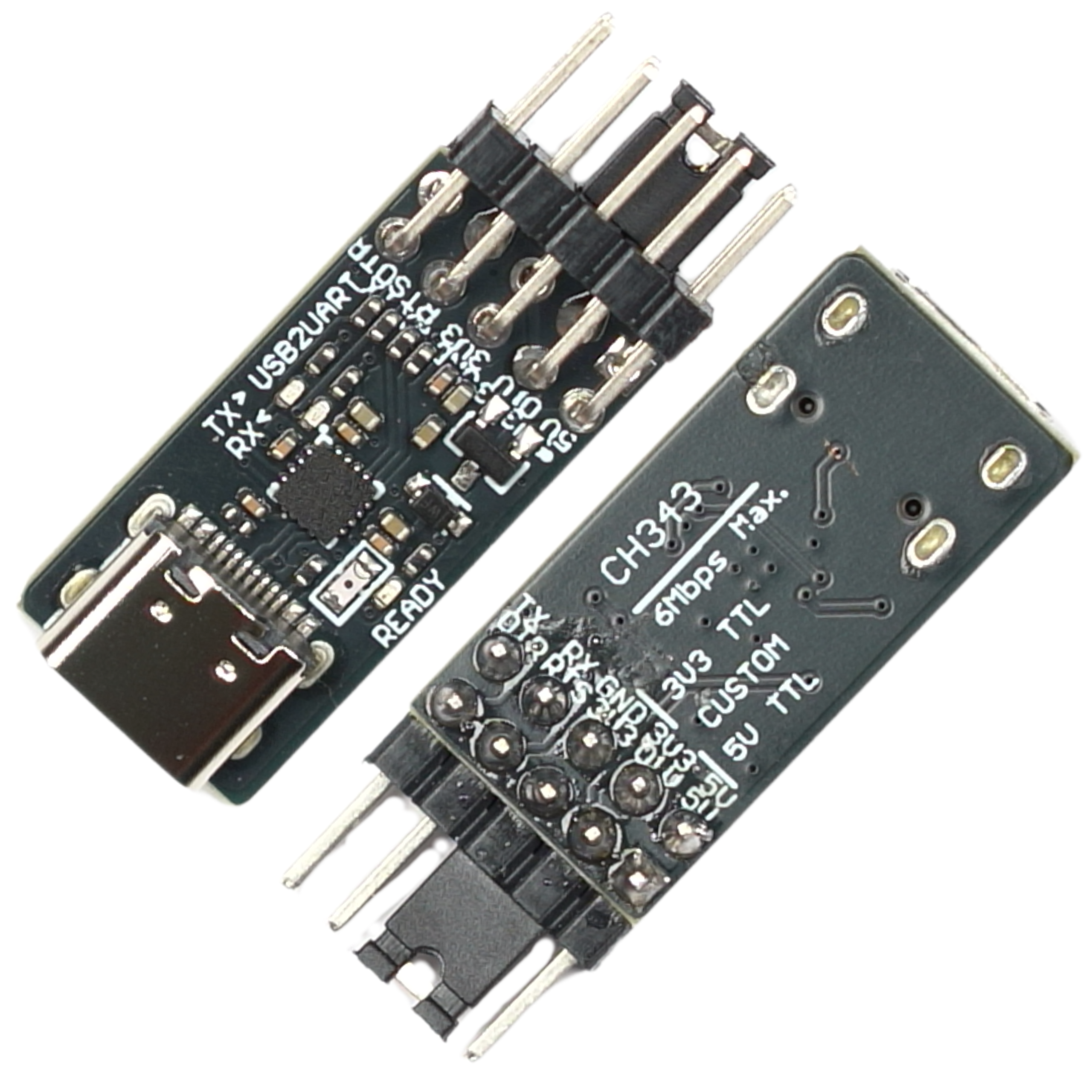
Thanks to jumpers, you can select a logic level of 3.3V or 5V, ensuring compatibility with most popular chips on the market.
Key Technical Features
- Chip: CH343P
- Interface: USB Type-C
- Logic voltage: 3.3V / 5V (set via jumper)
- Signal lines: TXD, RXD, GND, RTS, DTR
- Additional Pins: VCC, 3.3V, 5V, VOUT (jumpers-dependent)
- Data transfer rates: up to 6 Mbps
- System compatibility: Windows, Linux, macOS
- Connector: 2x5 gold-plated pins (2.54 mm)
- Dimensions: approx. 12.7 x 26 mm (excluding pins)
Benefits
- Ability to automatically program chips using the RTS and DTR lines.
- Fast data transmission reaching speeds of up to 6 Mbps.
- Versatile applications thanks to the option to select a logic voltage of 3.3V or 5V.
- Wide compatibility with popular operating systems.
- Stable operation and high compatibility with modern embedded systems.
Example Applications
- Programming and debugging ESP32 and ESP8266 microcontrollers.
- Serial communication with platforms such as Arduino, STM32, and Raspberry Pi.
- Working with communication modules: GSM, GPS, BLE, Wi-Fi.
- Creating diagnostic interfaces in automation systems.
- Prototyping and building your own DIY electronics projects.
How to use the logic level jumper
There are three marked positions on the board: 3V3 TTL, CUSTOM, and 5V TTL. The jumper sets the logic voltage for the TXD, RXD, RTS, and DTR lines—it must match the logic voltage of the connected device, otherwise there is a risk of damaging its GPIO pins.
- 3V3 TTL – set the jumper to this position when connecting 3.3V devices: ESP32, ESP8266, STM32, and most newer boards.
- 5V TTL – Set the jumper to this position when connecting 5V devices: classic Arduino Uno, Nano, Mega (older AVR chips).
- CUSTOM – do not install the jumper. Instead, use a separate wire to connect the VIO pin directly to the logic power supply line of the device you are connecting (e.g., 1.8V or 2.5V). The CH343P chip automatically detects and adapts to voltages in the 1.8V–5V range.
Note: The 3.3V and 5V pins on the board are not protected against reverse current. In CUSTOM mode, do not simultaneously connect the 3.3V/5V power supply from the converter to the same device that you are powering via VIO—this may cause a conflict between the two voltage sources.
Connection—example for ESP32
Using the RTS and DTR lines enables auto-reset during programming. Remember to set the jumper to 3V3 TTL (the ESP32 operates at 3.3V). Connection diagram:
- VCC – 3.3V (or 5V, depending on the chip)
- GND - GND
- TXD - ESP32 RX
- RXD - ESP32 TX
- RTS - IO0
- DTR - EN (RESET)
Shipping costs
The price does not include any possible payment costs
Product reviews (0)

All reviews (positive and negative) are displayed. We don't verify that they come from customers who have purchased the product.